Correct graphical representation of a Flowdrill connection is essential for clear communication between engineering, manufacturing and quality teams. This page provides standard guidelines for thread dimensions, drawing conventions and recommended annotations when documenting holes and threads produced by friction drilling and subsequent forming or tapping.
Because Flowdrill connections differ from conventionally drilled holes, accurate presentation in CAD and technical drawings ensures consistent interpretation across OEMs, Tier 1s and machining partners.

A Flowdrill joint is a thermally formed bush, and a thread that is created within the displaced material. This geometry cannot be correctly expressed using standard drilled-hole symbols alone.
Precise graphical documentation helps to:

Many engineers select standard features directly from a CAD library. Since Flowdrill geometries are not yet included in common online libraries, individual STEP files can be requested from Flowdrill.
These STEP models reflect the correct bush geometry, internal thread length and recommended tolerances.
The sketches below represent a typical drawing setup for Flowdrill connections. They include indications for:
A typical cross-section shows:
This section view ensures the manufacturer understands that the thread is fully contained within the formed bush and not inside the original sheet thickness.
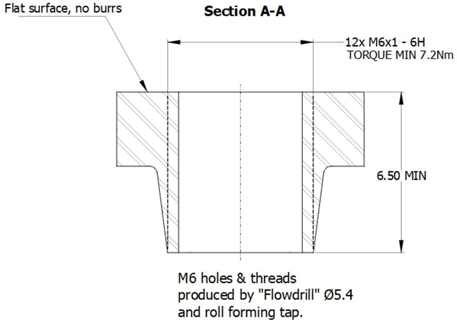
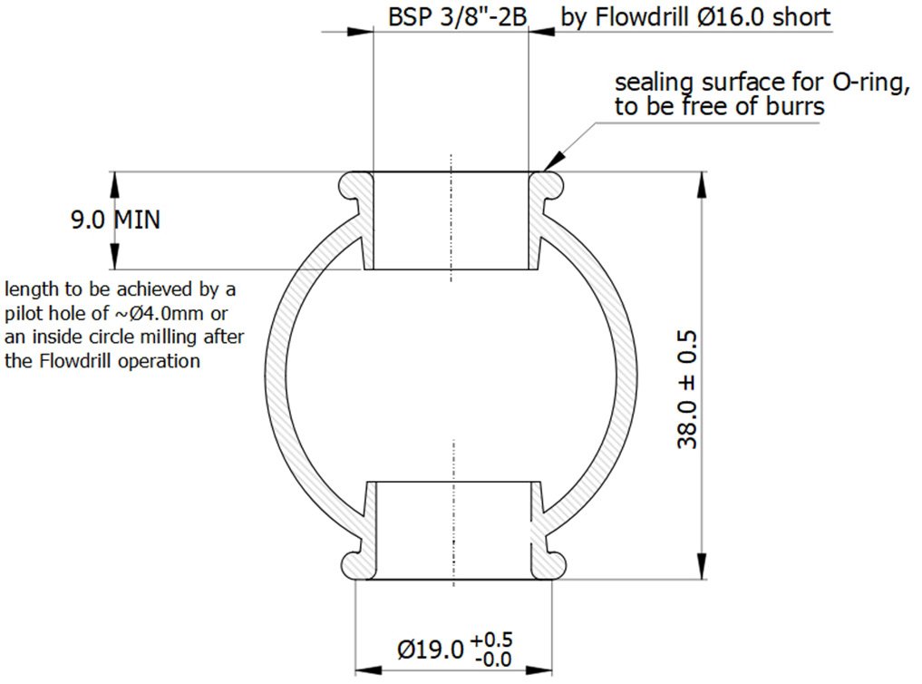
Include the following notes to avoid ambiguity:
These notes prevent downstream operations from altering the functional geometry of the bush.
If you require STEP models, customised drawing guidelines or help integrating Flowdrill connections into your CAD library, our engineering team can assist. Provide your required diameter, material and application, and we will supply the correct geometry.